


Player Monitor Devices (PMD) Performance Specification

1. Introduction
Rugby is a contact sport with intrinsic hazards. Player Monitoring Devices are worn by Players to determine various parameters of performance during matches. This Specification identifies mandatory requirements for Player Monitoring Devices without seeking to compromise the form or appeal of the game and with the overall goal being to promote player welfare and reduce the risks of injuries to Players as far as practicable.
This Specification sets out requirements for Player Monitoring Devices. General requirements relating to the ergonomics, construction, sizing and design of the equipment are specified. Performance requirements relating to impact attenuation and retention method are also provided, and the corresponding test methods are described.
This Performance Specification should be considered in unison with both Law 4 of World Rugby’s Laws of the Game and World Rugby Regulation 12 and the relevant sections therein.
2. Terminology
Player Monitoring Device (Device) – any Device which is worn by a Player and which is capable of determining, live or recorded, data about a Player’s movements or any physical aspect of their performance.
Retention System – that which is used to secure the Device to the body.
Radius of curvature – the radius of a circle formed with the curved part of a Device’s surface when looking at a cross- sectional view perpendicular to the top surface.
Rupture – damage to the Device as defined in Section 4.3.1
Stud – a steel stud as per that defined in Regulation 12 – Schedule 2, Figure 1.
g – the acceleration due to gravity. g (standard) = 9.80665 m/s².
3. The World Rugby Process to Achieve Device Approval
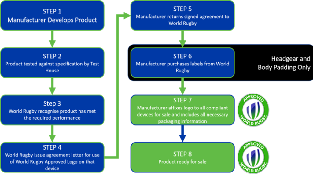
4. Manufacturers
It is the manufacturer’s responsibility to ensure that any product being sold or supplied for use in rugby has been previously tested in the laboratory by a recognized World Rugby Test House to ensure it meets the requirements set out in this specification.
The manufacturer should consult with a Test House to ensure that the correct components are submitted to enable the test to be carried out in accordance with this specification.
The minimum sizes and numbers of samples provided for testing must be in compliance with the performance specification.
Once all laboratory testing has been completed an application to use the World Rugby Approved Mark must be sought from World Rugby and all devices must display the approved logo at all times to be authorized for use.
5. Test House Requirements
To become a World Rugby Test House for Player Monitoring Devices a test house must comply with all of the following requirements:
5.1 Independence
The test house shall be wholly independent of any organisation involved in the design, manufacture or sale of any equipment permitted to be used by the Laws of the Game or World Rugby Regulations.
5.2 Equipment
The test house shall have the necessary equipment, with valid calibration certificates to complete all tests required in the Performance Specification. This equipment includes:
- Measurement device capable of measuring to 0.1mm increments
- Scales capable of measuring to 0.1g increments
- Method of reducing the temperature of samples to 0°C
- Thermometer or thermocouple capable of measuring at 0.1°C increments
- Humidity gauge capable of measuring to 1%
- Digital camera of minimum 12MB resolution
- A test machine with frictionless, or as close to frictionless as possible, rails capable of
- dropping a mass of 6.2kg (±0.05kg) from a height of between 0 and 150mm
- applying a vertical load of at least 2.5kN at a constant rate of 10mm/min (±0.5mm/min)
- A radius gauge with a measurement radius of 12mm (±0.1mm)
Any test house wishing to apply to become a World Rugby Test House for Player Monitoring Devices shall provide evidence and information on the equipment specified above to World Rugby along with any other information deemed relevant.
ISO 17025 certification is a prerequisite for World Rugby Test Houses.
There is no direct cost involved for holding the status of World Rugby Test House and a contract will be required to be signed before any test results will be accepted from applicants.
If you have any further queries or would like to apply to be considered for World Rugby Approved Test House status, please contact the Technical Services Department.
6. Testing Requirements
6.1 Ergonomics
Devices must be designed and constructed to minimise discomfort for the wearer. Normal playing movements shall not be impeded by wearing the Device.
6.2 Construction
6.2.1 Construction Materials
It is the manufacturer’s responsibility that all materials used in the construction of the casing of the Device shall not be significantly or materially affected by ultra-violet radiation, water, dirt, perspiration, toiletries, household soaps and detergents. All materials coming into contact with the wearer’s body will not be of the type known to cause skin disorders and shall not cause abrasion of either the wearer or other Players.
6.2.2 Retention System
Devices must be secured to a Player’s person via one of two methods:
- A pouch incorporated into the rear of the Player’s jersey; or
- A pouch incorporated into a harness to be worn by the Player under the jersey, which complies fully with all relevant requirements of Law 4, Regulation 12 and the Body Padding Performance
Whichever of those methods is used to retain the Device must ensure that the Device is held broadly in line with the Player’s T2 – T6 vertebrae, with its longest dimension parallel with the Player’s spine. The pouch must be small enough to ensure that the Device cannot rotate on any axis while worn by the Player.
Both methods must incorporate a padding material surrounding all sides of the Device which does not exceed 2mm thickness.
Padding materials must be homogeneous padding facing towards the wearer and must be the same texture, hardness and density as that facing the opponent). Foam padding of sandwich construction is not allowed.
6.2.3 Finish
Devices shall be so constructed that they will not cause any injury to the wearer or other Players during play.
6.3 Size, Weight and Shape
The declared dimensions of the Devices must be within the maximum and minimum dimensions detailed in Table 1 below, the actual dimensions measured by the test house must be within ±5% of these declared dimensions:

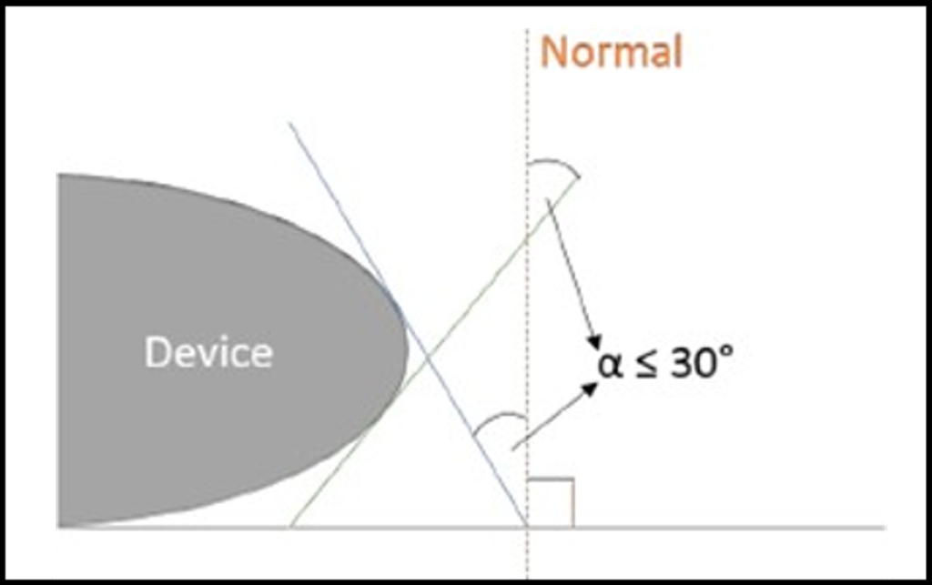
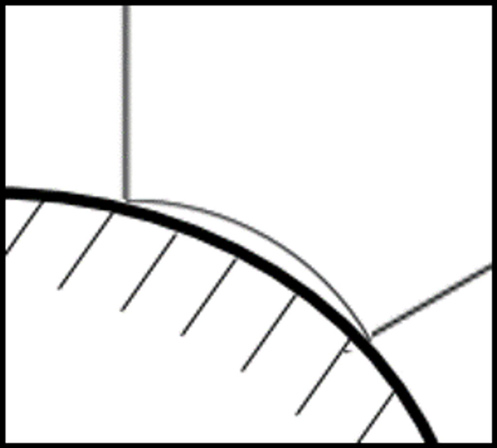
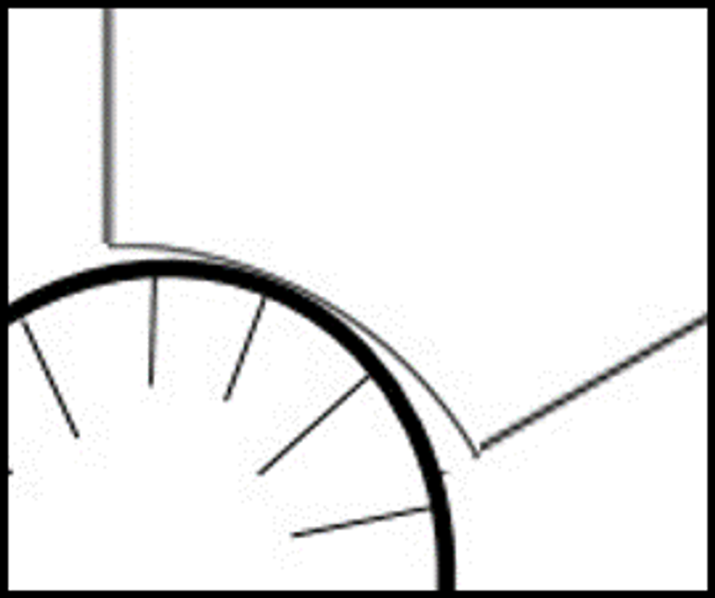
No surface of the Device may have a radius of curvature less than 12mm. This does not apply to:
- Markings, where the depth of any profile does not exceed 1mm
- Any surface which has a radius of curvature less than 12mm must have a tangent that is less than or equal to 30° from the normal where the normal is perpendicular to the Player’s back when worn in the manner prescribed by the manufacturer. See Figure 1
In addition, the following openings are permitted:
- Openings for fixings must not be greater than the equivalent area of a circle with a diameter of 5mm.
- Openings for connectors (charging points, etc.) must not be greater than 100mm2.
The mass of the Device shall not exceed 0.09 kg, including the weight of any battery devices within it.
6.4 Performance Requirements
6.4.1 Resistance to Impact Loading
When tested in accordance with the procedures specified in Section 4.4.5, the Device shall not rupture by any manner detailed in Section 4.3.1.
6.4.2 Resistance to Compression Loading
When tested in accordance with the procedures specified in Section 4.4.6 the Device shall be deemed to have failed if it ruptures under loads less than 1.001kN. If a Device ruptures under loads of between 1kN and 2.5kN, then it must be assessed for failure as detailed in Section 4.3.2. If the Device does not rupture under a load of 2.5kN then the Device will be deemed to have passed the dynamic loading requirements.
If, at any point a Device fails a testing requirement, the whole testing protocol must be stopped and the Device design determined to be non-compliant.
7. Test Methods and Procedures
7.1 Sampling
Two distinct test pieces are required:
- Empty Device casings
- Full Devices, that is a Device which includes all parts required to function properly and as intended to be worn by an
A total of 20 empty Device casings and 5 full Devices are required for testing.
It is recommended that all empty Devices are tested for all conditions prior to the full Devices being tested.
7.2 Conditioning of Specimens
- Test specimens must be in a new, un-used and un-tested
- The test specimen must be prepared by being conditioned for 12 hours at 0±2°C or 23±2°C depending on the test requirements and at an ambient
7.3 Testing Conditions
7.3.1 Rupture
A Device will be deemed to have ruptured if the casing changes shape permanently as a result of any of the modes:
- Fractures – When the surface of the Device cracks or fractures resulting in any part protruding beyond the level of the original (pre-test)
- Shatters – When one or more fragments are detached from the body of a Device into one or multiple small, sharp
- Undergoes plastic deformation – When the form of a component is permanently altered. The form will not have changed if the original features as measured for Section 3 are met while disregarding any punctures (holes made by the stud penetrating the device).
7.3.2 Impact Loading failure
A Device will be deemed to have failed the impact loading test if it ruptures (as defined in 4.3.1 above).
7.3.3 Compression Loading failure
A Device will be deemed to have failed the compression loading test if it shatters (as defined in 4.3.1 above) or any sharp, jagged edges, including those of internal parts of the full Devices tested, protrude from the surface of the Device.
7.4 Test locations
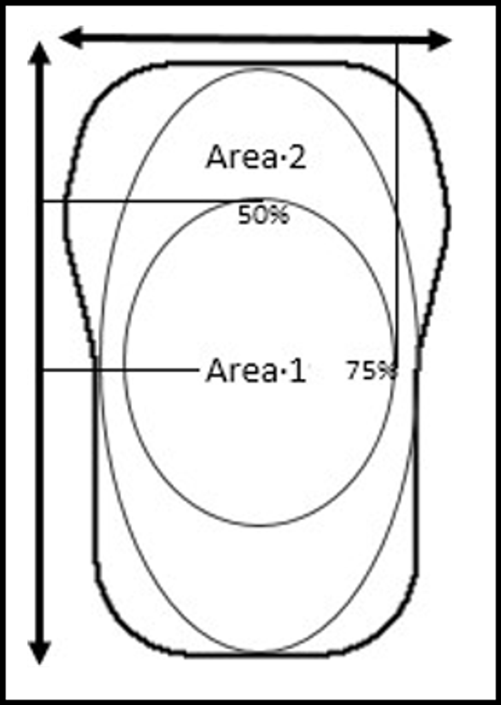
The Device is tested at points within two areas (Area 1 and Area 2) where the product is deemed to be most prone to fracture. The points chosen within these areas are tested repeatedly and are determined by the tester from specifications detailed in Section 7 which lead the tester to determine them as the structurally weakest points.
The two areas are produced from the centre point of the product, when viewing it in plan-view as it would be secured to a Player’s back (pursuant to paragraph 3.2.2 above). This is determined by finding the midpoint of the topmost face from the length and width of the Device. When the midpoint has been determined, Area 1 is calculated to 50% ±1% of the full height and 75% ±1% of the full width from the centre point. Area 2 is defined as the largest elliptical area which can be created where no edge overlaps the edge of the Device. The area encompassed by Area 1 is not included in Area 2, so that the two locations cannot both be located within area 1.
7.5 Impact Load Testing
7.5.1 Principle
The Device is impacted with a metal stud and assessed for damage.
7.5.2 Apparatus
The following apparatus is required:
- A method of reducing the temperature of the sample to 0°C ±0.1°C.
- A humidity gauge capable of recording to ±1%
- A thermometer or thermocouple capable of recording temperatures at 0.1°C increments
- A camera capable of producing a digital record of all features pre and post
- Double-sided adhesive tape 10x30 ±1 mm with a thickness of 0.15 ±0.1 mm and an adhesive strength of at least 15 ±5N/cm to steel shall be used to secure the Device to the steel
- Distance measuring Device capable of measuring to 0.1mm increments
- A stud, as defined in Section 2 above, which is free from visual
- A test machine which includes:
- A test area that allows the Device to be laid horizontally across a steel plate of a minimum thickness of 10mm. There must be a clear surround on the plate of 15mm in all directions when the sample is
- A steel frame capable of dropping a mass of 6.2kg ±0.050kg vertically on guide rails from various heights between 0mm and 150mm from the top of the fixed sample. Care must be taken to ensure the friction between the mass and the guide rails is kept to a minimum (free slide). The guide rails must be frictionless or as close to frictionless as possible. This should be verified by measuring the free drop acceleration which must be within 5% of the theoretical acceleration due to gravity.
- A means of securely connecting the stud to the mass in a manner which ensures that it is the only item striking the device
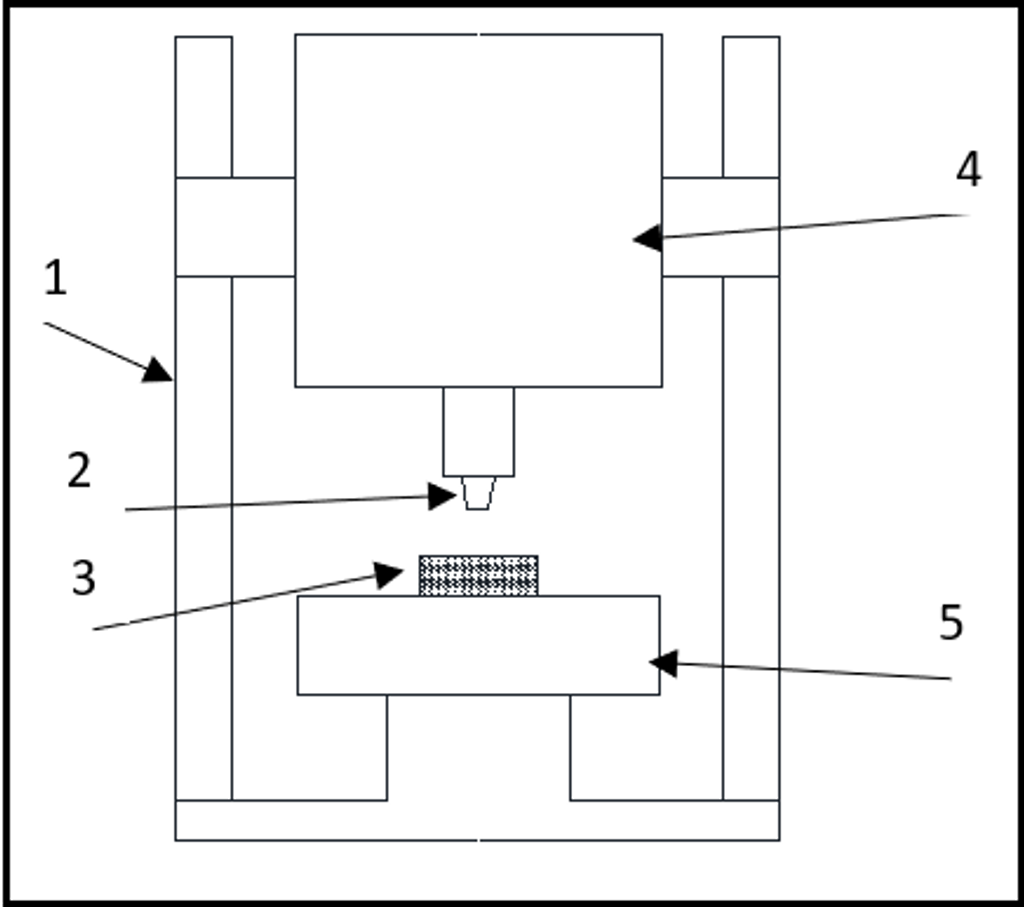
- Guide rails 2. Stud 3. Test Specimen
- Drop Mass 5. Steel base plate
7.5.3 Procedure
- The stud is fitted onto the drop mass in order to make contact with the
- Adhesive tape is applied between the base plate and the GPS unit as stated in 4.4.5.2
- The maximum dimensions of each Device along all 3 axes are measured accurately and
- The Device is positioned so that the stud impacts the appropriate identified test location stated in Section 4.4. The impact of the stud and drop mass shall not dislodge the Device from its position when impacting otherwise the results obtained should be
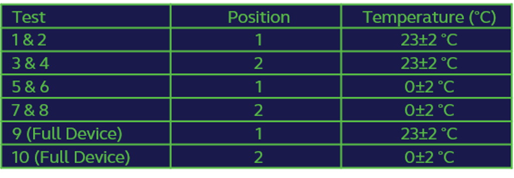
- The impact assembly (weight and stud) is positioned to drop from a distance of 30±0.2mm between the top surface of the test specimen and the bottom surface of the stud. Table 2 details the testing schedule (each test must be conducted using a virgin test specimen).
- The impact assembly is released to drop through free fall so that the stud impacts the Device at the required
- The Device is assessed for failure as per the specification in Section 4.3
- The maximum dimensions of each Devices along all 3 axes are measured accurately post-test and recorded.
- Full Devices (tests 9 and 10) shall only be tested if and when all other Devices are deemed to have passed the
7.6 Compression Load Testing
7.6.1 Principle
The Device is exposed to an increasing compression load until it ruptures, or the applied load reaches 2.5kN.
7.6.2 Apparatus
- A freezer to reduce the temperature of the sample to 0±0.1°C.
- A humidity gauge capable of recording to ±1%
- A thermometer or thermocouple capable of recording temperatures at 0.1oC
- A camera capable of producing a digital record of all features pre and post
- Double-sided adhesive tape 10x30 ±1 mm with a thickness of 0.15 ±0.1 mm and an adhesive strength of at least 15 ±5N/cm to steel shall be used to secure the Device to the steel
- Distance measuring device capable of measuring to 0.1mm increments
- A stud, as defined in Section 2 above, which is free from visual
- A test machine such that:
- The specimen can be laid horizontally across a steel plate of a minimum thickness of 10mm with a minimum of 15mm free space around the
- The load can be applied vertically at a constant rate of 10 ± 5mm/min.
- A load up to 2.5kN can be applied to the
- The force applied to the test specimen can be read with a maximum error of 1% and can be recorded.
- Load applicators can be attached as per two testing conditions:
- A stud securely connected to the underside of the moving plate in a manner which ensures it is the only part of the moving plate which contacts the
- Plate testing – A steel plate with minimum dimensions of 15mm larger than the test specimen in all horizontal directions and a minimum thickness of 10mm.
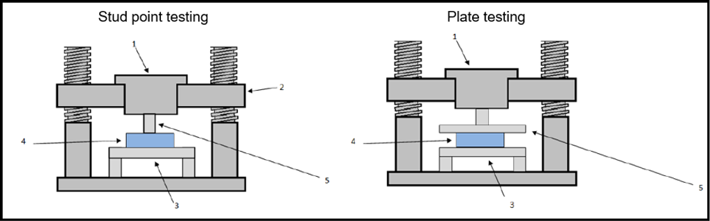
- Load Cell 2. Moving Crosshead 3. Steel Plate
- Test Specimen 5. Load Applicator
7.6.3 Procedure
- Ensure the steel plate and load applicator are free of
- Rest the Device on the steel plate with the identified test location directly below the appropriate load applicator as shown in Figure 4 securing with the double-sided adhesive tape between the test specimen and the steel
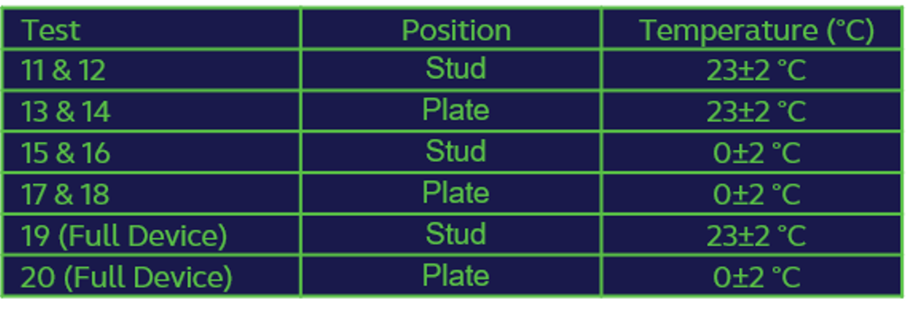
- Vertically apply the load on the test specimen by means of the specified test machine at 10mm/min until the maximum load of 2.5kN is reached, utilising the appropriate load applicator for the test being conducted (plate or stud).
- Plot the resulting Force/Extension
- Photographic images must be taken as per Section 5.1
- For the 0°C testing conditions the testing must be commenced on a rising thermometer and testing must be completed before the Device temperature rises to 5.1°C.
- Full Devices shall only be tested if and when all other Devices are deemed to have passed the
7.7 Radius of Curvature
7.7.1 Principle
The external form of the Device is checked to ensure all parts required have a radius of curvature greater than 12mm, and thus no sharp edges.
7.7.2 Apparatus
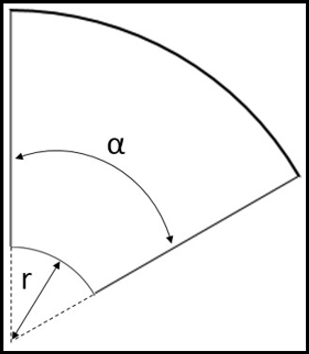
An appropriate radius gauge, made of metal (steel or aluminium) and not more than 2mm thick shall be used. The shape of the gauge is shown in Figure 5, where r shall be 12mm ±0.1mm and α shall be 60° ±2°.
7.7.3 Procedure
For all profiles of depth greater than 1mm ±0.1mm place the gauge in the areas of minimum radius of curvature of the area to be tested. If both ends of the gauge touch the surface of the Device then that area passes the requirement. Figure 6 illustrates the procedure and the pass and fail conditions.
8. Reporting
8.1 Images
Photographic images of each Device prior to and post testing are taken. Images must be on a plain background and well lit. Sufficient images must be taken of the Device including at least a plan, elevation, end elevation, and detailed views of any failure that occurs.
In addition, any data whether in table or graph form recorded during testing shall be reported.
8.2 Test Report
The test results and all other required information shall be reported using the World Rugby Player Monitoring Device Testing Report.
9. Product Marking
Devices shall be permanently marked with the following information by the manufacturer once compliance with this specification has been achieved:
- Name or trademark of the
- The World Rugby Approved logo, permanently visible on the
- Any other markings required by any applicable regulations in the territory of
10. Manufacturer’s Declarations
When submitting Devices for testing to testing institute, the manufacturer must provide a schematic of the Device design, including dimensions, with plan views of both sides of all assembly components for the casing and cross- sectional views along the length and width of the assembled casing.
11. Disclaimer
Whilst every effort has been made to ensure the accuracy of the information contained in this document any party who makes use of any part of this document in the manufacture of rugby headgear (a "User") does so at its own risk and shall indemnify World Rugby their officers, directors, servants, consultants and agents against all claims, proceedings, actions, damages, costs, expenses and any other liabilities for loss or damage to any property, or injury or death to any person that may be made against or incurred by the World Rugby arising out of or in connection with such User's use of this document.
Compliance with the requirements detailed in this document by a User does not of itself confer on that User immunity from legal obligations. Compliance with the requirements detailed in this document by a User constitutes acceptance of the terms of this disclaimer by that User.
World Rugby reserves the right to amend, update or delete sections of this manual at any time as deemed necessary. This World Rugby manual may not be reproduced in whole or in part in any manner without the permission of World Rugby.