


Studs and Outsoles Performance Specification

Last Updated: 01/01/2019
1. Introduction
Rugby studs and general outsole designs developed to provide sufficient grip to players are a key factor in enabling players to play the game at a high level.
Parallel to this is a need to provide guidance on the performance of such stud and outsole designs so that the inherent risks to players from contact with these components are minimized.
This specification sets out the considerations that should be made when considering the suitability of designs, the opinion of a referee can and should overrule any findings from the tests listed in this specification.
Studs/cleats of player’s boots must conform with this World Rugby Specifications (Regulation 12), must not be longer than 21 mm, and must not have any burring or sharp edges.
This Performance Specification should be considered in unison with both Law 4 of World Rugby’s Laws of the Game and World Rugby Regulation 12 and the relevant sections therein.
2. Manufacturers
It is the manufacturer’s responsibility to ensure that any product being sold or supplied for use in rugby has been previously tested in the laboratory by a recognized World Rugby Test House to ensure it meets the requirements set out in this specification.
The manufacturer should consult with a Test House to ensure that the correct components are submitted to enable the test to be carried out in accordance with this specification.
The minimum sizes and numbers of samples provided for testing must be in compliance with the performance specification.
3. Test House Requirements
Information on the qualifying criteria for and applications to become a recognised World Rugby Test House should be made to the World Rugby Technical Services Department.
4. General Design Guidance
4.1 Three main injury mechanisms are prevalent during play:
- Glancing
- Raking
- Stamping
In each case one or more studs/cleats on the boot sole may contact the other player depending on circumstances. The worst-case scenario in any event will be when a single stud/cleat, normally one toward the edge of the sole, makes contact alone.
The main factors regarding individual stud/cleat design are: shape, profile, length, radius of edges, hardness, propensity to burring, and rate of wear (the latter being with respect to exposing other internal materials/components).
The design of studs/cleats needs to be considered in both plan and profile view, and also with respect to both contact area and radius of curvature. Contact area relates to contact pressure and hence the risk of bruising to, and penetration of, a player’s skin. Radius or sharpness of edges relates to risk of cutting the skin.
In addition, there are whole sole design factors to consider including sole rigidity and edge profile.
The following summarises many of the potential risk factors that should be considered - the list is not exhaustive:
4.2 Design & Dimensions
- Assessment against geometric
- This approach can be used to assess conventional conical stud
- For assessing other stud designs testing may be
4.3 Strength & Durability of Materials & Construction
- Impact resistance with respect to risk of stud/cleat
- Impact resistance with respect to risk of a stud/cleat detaching during play and leaving a dangerous protrusion or
- Risk of damage to studs/cleats resulting from the process of fixing and removing them (and/or (blanking plates) from the boot and that could introduce an injury
- Wear resistance with respect to risk of burring or exposing dangerous internal components
4.4 Performance Tests
- Glancing skin injury – before and/or after real or simulated
- Raking – before and/or after real or simulated
- Stamping – before and/or after real or simulated
4.5 Labelling & User Instructions on:
- Attaching/removing studs/cleats, if
- Fixing blanking plates, if
- Care and maintenance respect to safety
- Replacing studs/cleats at wear limit, if
- Assess and report any other risks not covered by the
Attention is also drawn to legislation such as the EU General Product Safety Directive (92/59/EEC), which applies to all products sold within the European Union. Equivalent or similar legislation may apply in other countries or regions of the world.
4.6 General Guidance
The following guidelines provide guidance on the design, dimensions and performance of rugby studs/cleats. Suitable performance tests are suggested which can be used to evaluate the performance of new stud/cleat designs.
4.6.1 Materials
- Materials used in the studs/cleats should be such that they do not give rise to hazards as a result of mechanisms such as abrasion or impacts in wear; or through any other form of damage or deterioration. Materials used in replaceable studs/cleats should be capable of repeated fixing and removal without creating a
- Nylon has been found previously not to be a suitable material due to its propensity to
4.6.2 Shape & Dimensions
- Stud/cleat length shall be no greater than 21 mm (see Law 4).
- Studs/cleats complying with the design and dimensions shown in Figure 1 should give satisfactory performance.
- The shape and dimensions of other stud/cleat designs should be such that they present a no greater risk of injury to another player than the stud/cleat shown in figure 1. Tests A and B can be used to assess comparative
- The plan view cross-sectional contact area of the stud/cleat shown in Figure 1 at a plane 2 mm below the tip is 78 mm2. Other studs/cleats having the same or greater contact area might be expected to give satisfactory performance dependent on minimum stud/cleat width in any
- All edges of the studs/cleats should be finished smooth and rounded to a radius of not less than
4.6.3 Construction & Design
- The edge profile of the sole unit itself should be rounded with no sharp
- The studs/cleats should have no external projections on its surface except where text or a logo is In such cases, the embossment details shall be no more than 0.3 mm proud of the surrounding material of the stud.
- The studs/cleats and their attachment should be capable of withstanding mechanical demands of service, including impacts and abrasive wear, without becoming damaged and creating a potential hazard. Performance can be assessed by means of tests C, D and
- In the case of studs/cleats incorporating a spigot or similar, it is recommended that:
- when the attachment spigot is of a different material from the stud/cleat, a clearly visible warning should become evident when the stud/cleat has worn down to a length that gives a minimum of 2 mm cover to the end of the
- Any flutes or other recesses for the fixing tool, should not extend nearer to the tip of the stud/cleat than the clearly visible warning
- Replaceable studs/cleats should be designed in such a way that they can be fitted by a method that does not damage the stud/cleat and thereby introduce a cutting hazard or any other

Acceptable dimensions for conical or cylindrical studs/cleats are shown in Figure 1.
Also, the minimum diameter values together with the maximum length value also defines a “comparator” stud/cleat, made in aluminium, that can be used in performance tests to evaluate alternatively shaped studs/cleats.
4.7 Performance Tests – Optional
The principles for five tests are suggested:
Test A – Skin Glancing/Raking test
Test B – Skin Stamping test
Test C – Stud/cleat Impact test
Test D – Fitting of replaceable studs/cleats
Test E – Wear simulation
- Tests A and B provide a direct method of assessing a stud/cleat’s propensity to cause injury through glancing, raking or stamping
- Tests C and D assess the mechanical strength of studs/cleats and their attachment to the boot and thereby assess the risk of product failure resulting in a stud/cleat or boot sole becoming damaged and creating a potential
- Test E provides a means of assessing how studs/cleats may change in-service due to wear and indicate whether or not there is an increased risk of
- A schematic illustration of the principle of each test is given
- For tests A and B a suitable human flesh simulant is required comprising an artificial skin backed with a thick deformable muscle-like For example, a 1.5 mm thick poromeric shoe upper material having relatively low abrasion resistant may be used an artificial skin combined with gelatine, moulded into suitable form, as the deformable substrate.
- The performance criterion for tests A and B is that the stud/cleat be evaluated should cause no greater damage to the artificial skin than the reference stud/cleat defined in Figure 1
5. Test A – Skin Glancing/Raking test

This test assesses the risk that a stud/cleat may cut or otherwise injure other players as it slides or rakes across the skin. A simulated skin surface is subjected to a series of glancing blows by the stud/cleat, which is attached to the underside of a pendulum or equivalent device. In the test the tip, the flank and any integral mounting or fixture points come into contact with the simulated skin over a sliding distance of at least 70 mm (a pendulum device might require a spring loaded mechanism to achieve the sliding distance). The amount of damage to the simulated skin is compared with that inflicted by the comparator stud (Figure 1). In addition, the follow through swing of the pendulum can be recorded as the energy absorbed by the contact.
6. Test B – Skin Stamping test
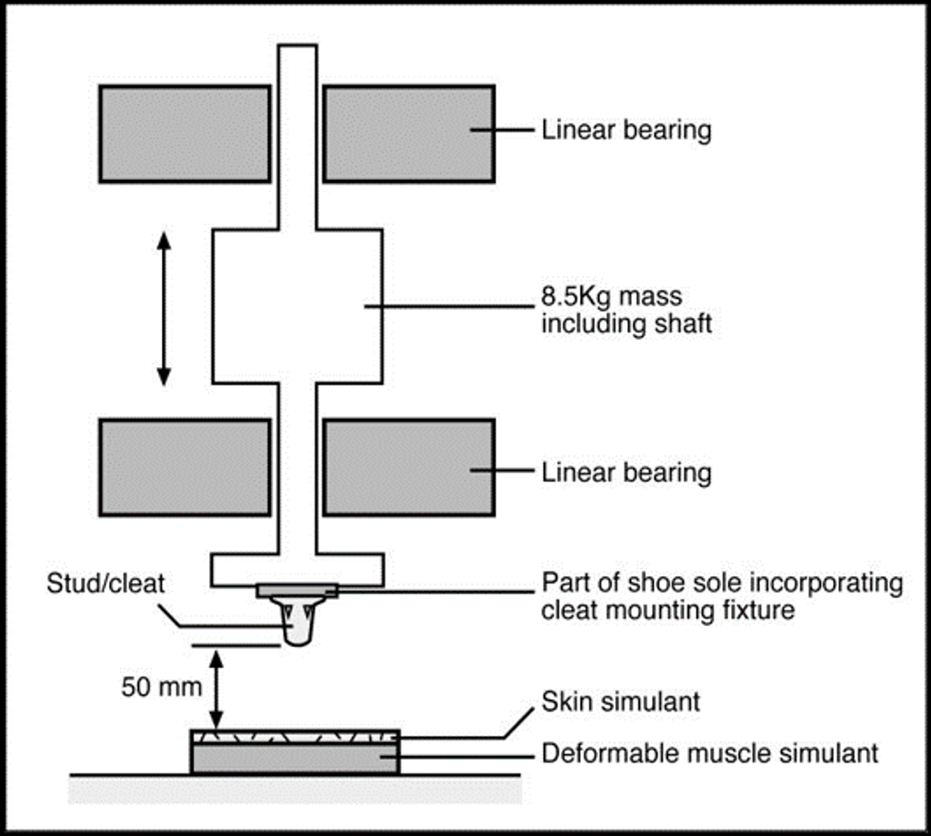
A falling weight impact test or equivalent means of replicating the impact forces at heel strike in running should be used. A mass of 8.5 kg dropped from a height of 50 mm would be a suitable approach.
The test rig should stand on a rigid, high mass base to eliminate energy losses through vibration.
The stud/cleat should be mounted securely by its base and including all parts of the mounting or fixing system, to either the moving or fixed part of the test in such a way that it impacts the skin/flesh stimulant (mounted on the other part) with the wearing face of the stud/cleat.
The depth of penetration of the stud/cleat into the artificial skin/tissue should be measured and compared with the value obtained with the comparator stud (Figure 1). Visual assessment of damage to the skin would also be made.
7. Test C – Stud/cleat Impact test

A stud/cleat, mounted securely by its base and including all parts of the mounting or fixing system, is subjected to a series of measured blows to its side from the striker of a ballistic pendulum or similar device. The energy of the blows is increased in steps until either the stud/cleat or its means of attachment fails or a specified energy level is reached without damage occurring.
It is suggested that when tested up to and including an impact energy of 8 J the stud/cleat tested shall:
- remain secured to the attachment system;
- not disintegrate or completely split;
- not show any fracture
If the impact of 8 J causes fine hairline splits or cracks, the test should be continued in steps of 0.5 J. The stud should remain secured to the attachment system and not disintegrate or completely split at impacts up to 12 J.
8. Test D – Fitting of replaceable studs/cleats
If the stud/cleat is replaceable then it should be fixed to, and detach from, the boot sole at least ten times according to the manufacturer’s instructions and using the tools provided, if any. Apply a torque or force level just over and above what might be considered ‘reasonable’ for a powerful rugby player. For example, a reasonable torque to apply to conventional screw-in studs is 1.5 N.m.
Inspect for any sign of damage that might increase the risk of causing injury in wear. Where such damage occurs, tests could be carried out according to tests A and B.
9. Test E – Wear simulation
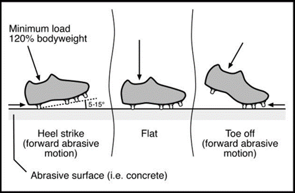
The principle of this test should be based on replicating the biomechanics of gait such that it reproduces the correct contact angles and loads between the boot and ground that occur in wear. The test cycle commences with the heel striking the test floor at a predetermined angle, and the vertical load increasing as the ‘leg’ rolls forward over the shoe-ground contact point, eventually transferring contact to the forepart of the shoe and finally toe-off. The vertical load achieved during the cycle should be at least 120% bodyweight. The floor used should replicate an abrasive, man-made surface such as concrete or asphalt that might be expected to be found around rugby pitches or in clubhouses.
Alternatively, simple trials, whereby players walk or run for say 400 m on a an abrasive, man-made surface, would suffice.
Inspect each stud/cleat for any sign of damage that might increase the risk of causing injury in wear. Where such damage occurs, tests could be carried out according to tests A and B.
10. Disclaimer
Whilst every effort has been made to ensure the accuracy of the information contained in this document any party who makes use of any part of this document in the manufacture of rugby headgear (a "User") does so at its own risk and shall indemnify World Rugby their officers, directors, servants, consultants and agents against all claims, proceedings, actions, damages, costs, expenses and any other liabilities for loss or damage to any property, or injury or death to any person that may be made against or incurred by the World Rugby arising out of or in connection with such User's use of this document.
Compliance with the requirements detailed in this document by a User does not of itself confer on that User immunity from legal obligations. Compliance with the requirements detailed in this document by a User constitutes acceptance of the terms of this disclaimer by that User.
World Rugby reserves the right to amend, update or delete sections of this manual at any time as deemed necessary. This World Rugby manual may not be reproduced in whole or in part in any manner without the permission of World Rugby.