


Headgear Performance Specification

1. Introduction
The use of padded clothing and in particular headgear has been prevalent in the sport of rugby since the mid 1990’s. World Rugby, at this time, looked to create a performance specification to ensure that use of these devices was conducted in a manner which did not materially affect the way the game was played. This specification for headgear, shoulder padding and breast padding looked to encourage players to protect themselves rather than providing equipment which would provide additional protection from potential injuries. The only injuries that headgear compliant with this specification are intended to protect against are cuts and abrasions.

The Headgear Performance Specification sets out general requirements for headgear relating to the ergonomics, construction, sizing and design of the equipment. Performance requirements relating to Impact Acceleration Attenuation and retention system strength and effectiveness are also provided, and the corresponding test methods are described. In addition, requirements for product marking and instructional literature are included.
Headgear compliant with this regulation, and thus with limited Impact Acceleration Attenuation properties, is not intended nor expected to protect against any form of mild traumatic brain injury or skull fractures. The additional requirements of this regulation are in place to enable these devices to be used in a way that does not pose additional risk to the wearer or other players coming into contact with them.
World Rugby believe that putting the duty of care on the player to perform within their physical limits is a more effective injury management method than allowing for the use of clothing that has high Impact Acceleration Attenuation properties.
This Performance Specification should be considered in unison with both Law 4 of World Rugby’s Laws of the Game and World Rugby Regulation 12 and the relevant sections therein.
2. Terminology
Headgear – padding worn on the head
As-worn – indicates the way the manufacturer intends a player to wear the device. Except where explicitly required, it shall be assumed that all tests and measurements are completed in this orientation.
Inside-out – indicates the inverse of as-worn, where the internal surface becomes the external surface.
Devices – The assembly of fabrics, pads, labels, and other elements that may go into the construction of headgear and are part of the device as intended to be worn by players during a match.
Retention System – that which is used to secure the headgear to the body.
Sample – an individual device submitted for testing.
Padded area – a section of the device that incorporates an impact force attenuating layer in addition to the basic fabric(s) used to hold these layers together.
Hang tag – a tag attached to an article of merchandise giving information about its materials, proper care, and use.
Manufacturer – any entity involved in the manufacture of body padding devices, excluding any entity involved in only constituent parts of a headgear device.
Brand – the entity whose name is printed on the device or on the packaging of the device when sold.
Accredited Test House (ATH) – an independent laboratory recognised by World Rugby as being competent to test against the requirements of this Performance Specification. Information on the qualifying criteria for ATHs can be found on the World Rugby website.
g – indicates the acceleration due to gravity at sea level (approximately 9.81 m/s2).
For the avoidance of doubt, any reference to the word “should” within this document indicates that it is recommended but optional for consideration.
Any reference to the word “shall” indicates a requirement of this performance specification and a corresponding assessment method will be
provided.
Where an assessment method is not provided it shall be assessed visually by the ATH.
3. The World Rugby Process to Achieve Device Approval
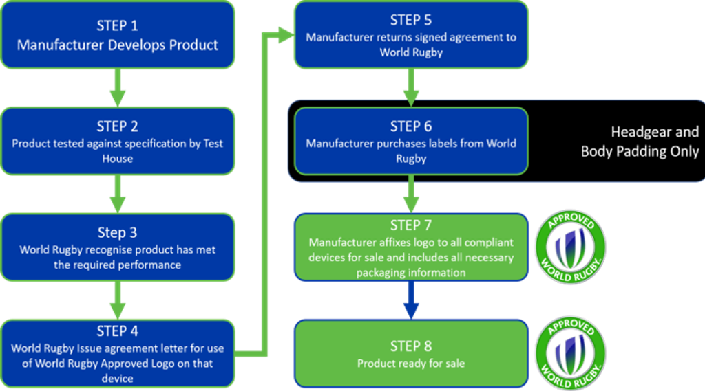
4. Manufacturers
It is the Brand’s responsibility to ensure that any device being sold or supplied for use in rugby has
been tested in the laboratory by a recognised ATH to confirm that it meets the requirements set out in this specification.
The brand should consult with an ATH to ensure that the correct components are submitted to enable the assessment to be carried out in accordance with this specification.
Once all testing has been successfully completed, the results shall be submitted to World Rugby by the ATH and an agreement signed by the brand to abide by the conditions of use of the World Rugby Approved Mark
5. Testing Requirements
All tests related to material properties or performance properties shall be conducted in both the as-worn and inside-out orientation in line with the test location requirements.
In the event of any ambiguity arising from the application of these requirements to a specific device, World Rugby reserve the right to decide on the correct interpretation on an individual basis.
5.1 Summary of testing requirements
All reports made related to this performance specification shall include results and information on the aspects of testing/assessment included in Table 1 along with any other relevant information
|
Test |
Conditions | Orientation |
Test |
Requirements |
|
Thickness |
Ambient | - |
Calipers |
≤ 12mm |
|
Hardness |
Ambient | As worn and inside-out |
ISO 2439 Method |
≤ 750N |
| High Temperature | ||||
|
Impact Acceleration Attenuation |
Ambient |
As detailed below
|
≥ 200g | |
|
Retention System Strength |
As worn | Static: Closed Dynamic: Open |
||
|
Retention System |
Combined load: Closed |
|||
|
Materials |
As detailed below | |||
|
Zone of coverage |
||||
|
Finish |
- |
6. Design
6.1 Thickness
Headgear including any fabric on each side of the padding shall not exceed an overall thickness of 12mm when uncompressed.
6.2 Zones of coverage
Headgear shall sit within the area indicated in Figure 1. Relevant dimensions of the zone of coverage are given in Table 2. It is not required that headgear cover this entire area, but it shall not cover any part of the head outside of these areas.
Figure 1 - Headgear Zones of Coverage

| Dimension | XXS | XS | S | M | L | XL | XXL |
| Head Diameter |
500 | 520 | 540 | 560 | 580 | 600 | 620 |
| Size |
6 ¼ |
6 ½ |
6 ¾ |
7 |
7 ¼ |
7 ½ |
7 ¾ |
| B | 56 | 58 | 63 | 70 | 75 | ||
| C | 81 | 85 | 89 | 97 | 104 | 106 | 108 |
| D | 132 | 136 | 140 | 147 | 155 | 158 | 160 |
| E | 50 | ||||||
| F | >25 | ||||||
| G | 25 to 30 | ||||||
6.3 Ear Aperture
Where the ear is covered, the ear aperture of the headgear shall be solid, cross mesh or similar design. The covering of the ear should not significantly reduce the ability of the wearer to hear adequately during use.
6.4 Vision
Horizontal field of vision – the headgear shall provide peripheral vision clearance of at least 105° to each side of the longitudinal vertical line (median plane), as shown in Figure 2, when the headgear is positioned in accordance with the manufacturer’s instructions.
Figure 2 - Headgear Horizontal Field of Vision

Figure 3 - Headgear Vertical Field of Vision

6.5 Ventilation
It is the manufacturer’s responsibility to provide for adequate ventilation in the headgear design.
6.6 Retention System
A retention system should be attached so that the headgear remains in its normal position during play. Where a chin strap is used to secure the headgear, it shall be affixed to both sides of the headgear and pass under the lower jaw in close proximity to the jaw and the neck. The minimum width of the chin strap shall be 15mm. Buckles or similar hard fixings shall not be used in line with Law 4. Soft, rubber buttons or Velcro © type fixing materials are acceptable
7. Performance
7.1 Hardness
It is permitted for headgear padding to be made of distinct layers, but these layers shall be tested in combination as one piece of padding. When tested using the methodology in ISO 2439 Method E at 65% compression in both orientations, the force recorded shall not exceed 750N.
The maximum of all forces recorded for all test locations when tested inside-out shall also be within ±75N of the equivalent value when tested as-worn.
The diameter of the platen used when testing to ISO 2439 shall be 60 ±5mm.
Hardness testing shall be completed in five (5) locations as-worn and five (5) locations inside-out that do not overlap. As far as possible, these locations shall not correspond directly with those indicated for impact acceleration attenuation testing, but they shall give a representative performance of all areas of the device.
7.2 Impact Acceleration Attenuation
When tested in accordance with the procedures specified below, the peak acceleration of impacts delivered to test locations shall not be less than 200g when tested both as-worn and inside-out.
7.3 Retention
Headgear with a chin strap or similar shall comply with the retention system strength requirements indicated using the test method below.
All headgear shall comply with the retention system effectiveness requirements indicated using the test method below.
8. Construction
8.1 Ergonomics
Headgear should be designed and constructed to minimise discomfort for the wearer. All normal playing movements should not be impeded by wearing the headgear.
8.2 Materials
It is the headgear manufacturer’s responsibility that all materials used in the construction of the headgear should not be significantly affected by ultra-violet radiation, dirt, perspiration, toiletries, household soaps and detergents. Products should conform to ISO 15487 and ISO 22958. All materials coming into contact with the wearer’s body should not be of the type known to cause skin disorders and should not cause abrasion of either the wearer or the other players.
Manufacturers should also consider using recycled and or recyclable and environmentally sustainable materials and processes when designing their devices.
8.3 Finish
If distinct layers are used, the external layers on both sides shall be the same material.
All edges shall be smooth and rounded. In line with Law 4 of the Laws of the Game of Rugby Union, and except where allowed for elsewhere in this performance specification, there shall be no rigid materials that could harm the wearer or other players during normal use.
8.4 Conditioning of Specimens
Prior to impact testing, one specimen will be exposed to ambient conditions and another to high temperature conditions as follows:
- Ambient Temperature - one sample is conditioned by exposing it to a temperature of 20°C +/- 2°C and relative humidity condition of rh60% +/- 5% for a period of between 4 and 24
- High Temperature - the second is conditioned by exposing it to a temperature of 50°C +/-2°C and relative humidity condition of rh60% +/- 5% for a period of between 4 and 24
All testing shall be conducted within 5 minutes of removal from the conditioning environment.
9. Performance Testing
9.1 Sampling
Three (3) test specimens of each size shall be submitted by manufacturers, complete with ‘information supplied by the manufacturers’ indicated below. Two (2) specimens shall be used for impact acceleration attenuation and hardness testing at the various conditions and one for retention system testing.
9.2 Conditioning
Samples shall be stored for at least 4 hours at the required conditions, as detailed in Table 3, prior to testing. If testing is not possible when the device is at the high temperature conditions, then the tests shall be carried out as close as possible to these conditions but not lower than ambient conditions within 5 minutes of removal from the conditioning environment.
| Condition | Ambient | High Temperature |
| Temperature (°C) | 20 ±2 | 50 ±2 |
| Relative Humidity (%) | 60 ±5 | |
10. Test Methods
10.1 Impact Acceleration Attenuation Test
10.1.1 Principle
The headgear is mounted on the test headform so that the headform can be oriented in different positions and dropped on an anvil. The acceleration and time history of the impact shall be recorded using a tri-axial accelerometer and appropriate instrumentation. Peak acceleration and time duration data obtained using the methods specified below are used to determine the impact characteristics of that location.
10.1.2 Apparatus
The apparatus for the impact acceleration attenuation test shall consist of the following items (see also, Figure 4).
Figure 4 – Impact Acceleration Attenuation

- Headforms – All headforms used shall comply with EN 960, be without hair, be of metal and have a resonance frequency of at least 3kHz.
- Anvil – the anvil shall consist of a flat steel surface of diameter 130 ±3mm and not have a resonance frequency liable to affect the test results. The centre of mass of the headform shall lie over the centre of the anvil or as close as possible.
- Guide Assembly – a headform shall be attached to a free fall or rail guided drop assembly carriage by an adjustable mounting or other means that will allow impacts to be delivered at any prescribed point on the headgear.
- Accelerometer – a set of three accelerometers in a three-axis array are mounted at or close to the centre of gravity of the headform when the headform is mounted on the freefall carriage.
- Impact Recording and Displaying Instrumentation – the impact shall be recorded, displayed,and stored using instrumentation which is capable of resolving the gmax of the headform during testing.
10.1.3 Method
Reference Testing
A flat MEP (modular elastomer programmer) reference surface will be used measuring 150 ±2mm diameter, 25 ±1mm thickness mounted on a matching steel base. The bare headform will be dropped onto the MEP impact surface from a distance of 300 ±5mm. Resolved gmax values recorded by the accelerometer on three successive drops shall lie within ±10g of their mean.
Impacting
The headgear is matched for best fit to the test headform according to the manufacturers sizing. Each headgear is impacted in the general areas indicated in Figure 5 (crown, forehead, and temple/sweatband areas). An energy level of 13.8 ±0.5J shall be used for impact. This is equivalent to the ‘J’ headform falling through a height of 300mm. The fall height will be adjusted depending on the mass of the headform.
The impact zones will be the same for both as-worn and inside-out orientations:
- Once, where crown padding is
- Twice where forehead padding is
- Twice where temple padding is
Figure 5 – Impact Areas

Calculations and Reporting
Maximum acceleration
The maximum peak acceleration is calculated by measuring the perpendicular distance to the trace baseline from the midpoint of the resultant trace at maximum excursion and multiplying by the sensitivity factor. The sensitivity factor is defined as g per division deflection of the trace.
Duration of Impulse
Determine the duration of the pulse by measuring the total width of the trace along the 150g line in milliseconds.
10.2 Retention System Testing – Strength
10.2.1 Principle
The chin strap of the headgear is subjected to two loads. The first, a static load under which the strap will not open or break. The second is an additional load which falls dynamically to apply a sudden downward load causing the strap to open or break.
10.2.2 Apparatus
A suitable set-up is shown in Figure 6. The headgear is positioned on a test headform.
Figure 6 – Retention System Strength

- A support for the headform.
- A vertical guide assembly with an anvil is attached below the headgear with two round pins of diameter 12 ±1mm and 76 ±2mm apart (between centres). The total mass of the guide assembly with anvil is 7 ±0.02kg. A drop weight of 10 ±0.2kg can be moved up the guide assembly and dropped onto the anvil in a substantially frictionless fall through a distance of 300 ±5mm.
10.2.3 Procedure
- The headgear is mounted on the test headform, and the retention system is adjusted so that the headgear is securely positioned.
- The guide assembly is attached to the chin strap of the headgear to apply the static load.
- The small mass is dropped through 300 ±5mm exerting a dynamic load onto the retention system.
10.2.4 Interpretation
- If the system releases or breaks under the static load, it will be deemed to have ‘failed’.
- If the system does not release or break under the static load but releases or breaks when the additional dynamic load is applied, it will be deemed to have ‘passed’.
- If the system does not release of break when the additional dynamic load is applied, it will be deemed to have ‘failed’.
10.3 Retention System Testing – Effectiveness
10.3.1 Principle
The headgear positioned on a headform is subjected to a tangential force at the rear edge of the headgear in a forward direction. The resulting shock places a rotational load on the headgear. The headgear may be shifted but must not roll off.
10.3.2 Apparatus
A typical apparatus is shown in Figure 7.
Figure 7 – Retention System Effectiveness

- The headform is mounted to a stand in the upright position. The stand shall be rigid enough to not materially flex during testing.
- A vertical guide assembly weighing 3 ±0.02kg in total is attached via a cable or strapping to a
hook which attaches to the rear of the headgear. The cable or strapping shall have an elongation of no more than 5mm per 300mm when loaded with a 22 ±0.1kg mass in the free hanging position. - A drop weight of 4 ±0.02kg can be moved up the guide assembly and dropped onto the anvil in a substantially frictionless fall through a distance of 175 ±5mm.
10.3.3 Procedure
- The headgear is mounted on the headform and fitted in accordance with the manufacturer’s instructions. The retention system, where it exists is adjusted for best fit.
- The hook is attached to the rear of the headgear and the other end of the cable or strapping attached to the guide assembly.
- The drop weight of 4 ±0.02kg falls through a height of 175 ±5mm before it hits the anvil, stopping its fall.
- The retention system is readjusted, and the test repeated a second time.
10.3.4 Interpretation
If the headgear rolls off the headform during either iteration of the test, then it will be deemed to have ‘failed’.
11. Product Marking
All headgear shall be permanently marked with the following information by the manufacturer and, where relevant, shall comply with the requirements laid out in ISO 8559-2:
- Name and/or trademark of the brand
- Size or size range
- Instructions on how to properly clean and maintain the garment
- Once approval has been secured, a World Rugby Approved Label
- Once approval has been secured, a copy of the World Rugby Approved Mark (as detailed within World Rugby Regulation 12) shall be printed/affixed in a secure manner, to the external back surface of the device. This mark shall have a diameterof no less than 12mm
- Any additional requirements set out in the territory where the device is for sale.
In addition to the device markings above, once approved, the packaging with which the headgear is sold shall include the following information:
- Where the device has external packaging, this packaging must include the messaging below from World Rugby in a format provided by World Rugby to the manufacturer/brand, including any minimum dimensions and resolution prescribed.
- Where the device has hang-tags, an additional tag must be included using the messaging in a format provided by World Rugby. This is in addition tothe external packaging requirement above.
Messaging to be included on all World Rugby Approved padded clothing devices:
“This headgear has been designed to reduce the risk of cuts and abrasions to the wearer’s body only, and any impact reduction properties exist solely as a secondary effect of meeting this aim.”
12. Instructional Literature
Devices shall be accompanied by or provide easy access to at least the following information:
- Instructions that describe proper use and fit
- Instructions to replace the device after it’s expected useful life
- Instructions on care and maintenance
- Instructions on the recycling and sustainability options available on disposal.
- Warning concerning the improper use of cleaning agents or any other factors affecting the integrity of the equipment
13. Disclaimer
Whilst every effort has been made to ensure the accuracy of the information contained in this document any party who makes use of any part of this document in the manufacture of rugby headgear (a "User") does so at its own risk and shall indemnify World Rugby their officers, directors, servants, consultants and agents against all claims, proceedings, actions, damages, costs, expenses and any other liabilities for loss or damage to any property, or injury or death to any person that may be made against or incurred by the World Rugby arising out of or in connection with such User's use of this document.
Compliance with the requirements detailed in this document by a User does not of itself confer on that User immunity from legal obligations. Compliance with the requirements detailed in this document by a User constitutes acceptance of the terms of this disclaimer by that User.
World Rugby reserves the right to amend, update or delete sections of this manual at any time as deemed necessary. This World Rugby manual may not be reproduced in whole or in part in any manner without the permission of World Rugby.